Rowandale Station & Town - Development History of Section One
Rowandale was started in 2012, but due to a
pending house move little progress was made till
late 2014. After the move, and once priority
renovation was completed on the new house, work
resumed on the Rowandale layout.
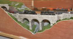
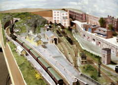
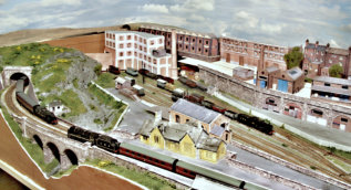
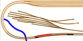
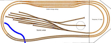
The first section, shown at top right, is how it was
prior to our house move; track all laid with a tunnel
entrance under a hill at bottom left and short
viaduct just before it.
The hidden sidings were temporarily modified to
enable connection to temporary ‘D’ loops to allow
continues running, as shown opposite.
The track has now reverted to the original design.
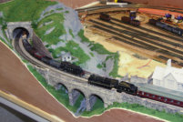
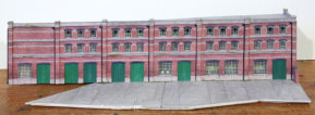
The short viaduct and tunnel have been
scratch built in card using photo realistic
texture sheets from the Scalescenes
range.
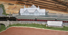
A mock-up of the station is in place and a
start has been made on the scenery.
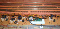
Miniature model aircraft servo motors
(Type SG-90) have been added to
operate the points; the servos being
mounted just in front of the rear storage
tracks and are connected to the points by
the wire-in-tube method.
The servos are controlled by the
Pololu Maestro Servo Controller, the large
bundle of wires to the servo’s can be
seen here.
The polarity of the frogs on the points are
set with micro-switches operated by the
servo motor arms.
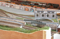
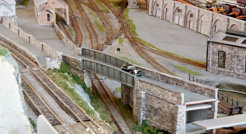
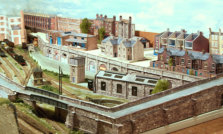
The station approach road and bridge has been
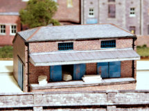
added, together with the station yard, small goods
store and groundwork in the goods yard, including
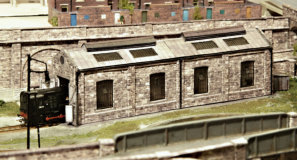
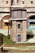
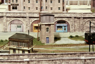
fencing. An engine shed, water tower and turntable
have also been built. The station building & large
factory at the rear are is still in mock-up form.
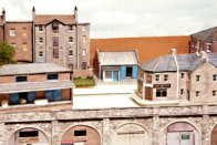
Retaining walls, with storage units and a couple of
shops under the arches, have been added at the
rear of the goods yard, with road access via a ramp.
A coal merchants office is also here. There is again a
mock-up of a factory unit with chimney.
Above the retaining wall, at the level of the main
town, some buildings are completed, whilst others
are under construction, or in mock-up form.
The front half of this raised section covers the servo
motors, which operate the points. The rear half
covers the hidden holding tracks. Both parts will
be removable in case access is needed to the
tracks & servos underneath. As well as completing
the buildings in this raised area, the roads and
garden & grass areas need to be constructed, and
the buildings set into it.
Some of the buildings were originally on the rear
of Archie’s Yard, which was originally intended to
be a quick lash-up, but did become a full layout.
Temporary semicircular tracks, on a ‘D’ shaped
board, have been added at the right hand end to
allow continuous running on the main line and
give access to the goods yard.
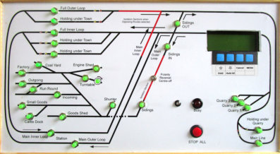
The Route Selection push buttons on the original front
panel were connected to a serial chain of resistors,
which sent an analogue signal to the Pololu Servo
Controller. This was then interpreted as a Route
Number, and the corresponding servos operated to set
the required points. Because of occasional electrical
noise problems on the analogue signal it was decided
to change over to using digital commands instead.
Initially an old industrial micro-controller was used,
as I had one left over from my working days.
However this was gross over-kill for the task, and
would be expensive to replace if it ever failed in the
future. Next a cheap PIC Micro-controller was used,
but was rather slow and the software did not easily
lend itself to multi-tasking, which made the software
development more complicated than it should be.
A Raspberry-Pi 3B was next tried, with great success.
The Raspberry-Pi is an amazing little computer,
designed and built in the UK, which uses an ARM
processor ( as used in many mobile phones).
It has HDMI output to a
monitor, four USB ports,
built in interfaces for
wired networking, WiFi
and Bluetooth; costing
just £30. Onboard, it
has 26 general purpose digital Input/Outputs
(GPIO), together with an I2C data bus through
which a very large number of remote digital I/O
can be controlled. It uses a micro SD card for
storing the Operating System and program code.
The usual operating system for the Raspberry-Pi
is the Raspian installation of Linux, together with
the Python high level language, which supports
program threads running in parallel, this proved
an ideal choice, for the new control panel.
The control of the speed of the locos is still using
the free open-source software JMRI DeCoder-Pro,
but instead of running on a laptop, it now runs on
a second Raspberry-Pi 3B.
It was possible to run both the Route Setting
procedures and the DeCoder-Pro software on the
same R-Pi 3B, but despite the 4 core processor,
sometimes the speed of response to commands
exhibited a slight delay.
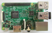
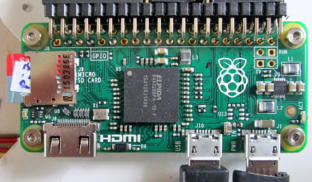
The Raspberry Pi Organisation have recently developed a
minimal version, the Raspberry Pi-Zero; see photo at right.
This model has only one processing core, the minimum of
interfaces, & is slower, but costs just £4. It has the same
digital I/O interfaces as the bigger model and is proving very
popular for small control tasks. On Rowandale one is now used
to drive a stepper motor to operate the turntable.
Programmed with the sequences for energising the stepper
motor coils ( via a driver interface ), a single push on the
control panel button, causes the stepper motor to turn the
table exactly one half revolution; with acceleration &
deceleration.
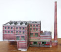
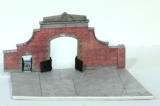
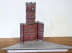
The large factory at far left, which covers the curved
tracks leading to the hidden sidings, is now finished,
together with it’s clock tower, associated low relief
buildings behind it, and the entrance gateway.
Internal fittings & people have been added.
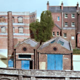
A low relief mill building has been added behind the
garage, completing the range of buildings covering the
hidden tracks. The industrial units have been set in their
yard areas with surrounding walls and suitable bits &
pieces, and workman positioned.
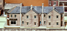
The back gardens have been added to the
cottages, attached to the pub. The row of half
relief cottages - which were used on Archie’s
Yard are yet to be replaced.
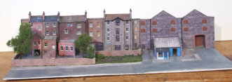
These buildings at the rear, which cover the
hidden tracks, and in the middle distance, which
hide the control units for the points and
sensors, are built as removable modules to
allow access to the tracks and the electronics.


The modules individually are shown in the gallery below.
See the page for detailed views of the buildings.
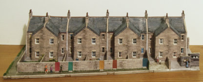
The final module over the servo motors is
this row of eight full depth cottages, which
have replaced the temporary half relief
ones - which were used on Archie’s Yard.
( No. The pigeons do not fly! )


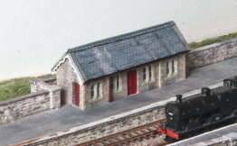
A start has been made on the scratch-built
station and waiting shelter, the latter is finished
and the bases for the main station walls cut-out.
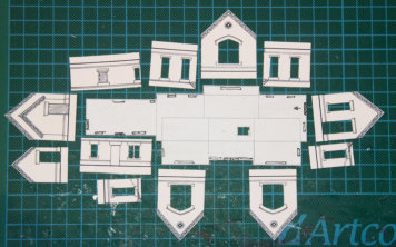
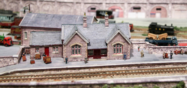
The main station building is completed, internal
lights fitted, together with internal passengers.
This a scratch built Midland Size 3 station. Built
using card with printed paper overlays; methods
learnt from the earlier Scalescenes kits.
More photos are on the Buildings Page.
Originally a Midland Size 2 station was planned, but
some excellent brass window & barge board frets
are available for the smaller station size, but not for
the larger one. Also this is probably a better fit for
the size of the town.

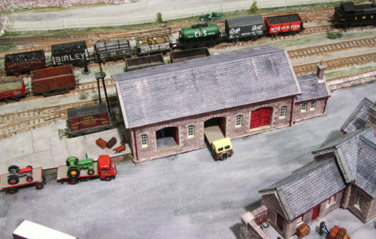
The main good shed is now completed, it has
internal lights and staff. It was also scratch built
to a standard Midland Railway design.

General tidying up and adding passengers,
porters and other staff and workmen,
completes this first phase of the layout.
The hidden sidings, at the rear, are about to be taken up
and reverted to the original plan ( shown at top of page )
and then will extend onto the next section of the layout,
to give space for longer trains.


Update
Menu
So that trains can be run again as soon as possible, these sections will
initially just have the track bases and track laid. Points control and isolation
sections will then be connected to the computer for route selection from the
control panel. Topography, buildings and scenery will then be added to each
section in turn.

The development of the sections of Rowandale; are each recorded on separate pages.
Photographs of this completed section are here:

